Remote Fuel Stop Valve 90° (TPX06–TPX09) — Technical review and buyer guidance
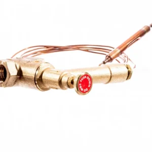
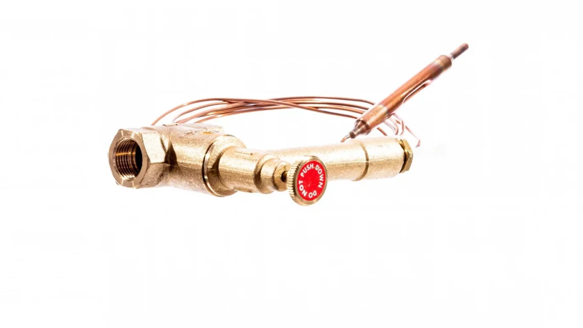
July 27, 2026The Remote Fuel Stop Valve 90° (often sold under codes TPX06–TPX09) is a straightforward, mechanically operated safety device intended to cut fuel to a domestic oil burner if the local temperature around the appliance climbs to the valve’s 90°C trigger point. It uses a capillary sensor and sensing bulb that forces the spindle to close the valve when the sensor is exposed to high heat. The unit must be manually reset after operation and is not designed for routine isolation.
What this device actually does — and what it doesn’t
At its simplest, the valve provides a second line of protection against an uncontrolled fire fed by liquid fuel. If a fire or dangerous overheating occurs adjacent to the burner or its casing, the sensing bulb will detect the temperature rise and the mechanical mechanism will close the valve, interrupting fuel flow. That can limit how much fuel reaches the appliance and therefore the potential for the fire to develop further due to continued supply.
What it does not do is replace normal safe practice. It is not a routine on/off valve for servicing, it does not reset itself automatically, and it is not a substitute for correct appliance siting, fire breaks, spill‑protection measures or regular servicing. It is a specialised safety component for systems where a passive, auto‑closing shut‑off in response to high local temperature is required.
Who should consider this valve — and who should look elsewhere
Suitable buyers
- Homeowners with oil‑fired domestic boilers who want an additional passive safety device between tank and burner.
- Installers specifying a low‑energy mechanical device that will close the fuel supply if the appliance area overheats.
- Systems where electrical shut‑offs are impractical or where a purely mechanical failsafe is preferred.
Not suitable
- Anyone who expects the valve to act as a service isolation valve — the manufacturer explicitly warns against using it for routine shut‑off during maintenance.
- Installations that require automatic reset after a trip (the valve requires a manual reset once it has closed).
- High‑pressure fuel systems or applications outside the valve’s stated pressure limits (maximum allowed pressure when closed is 1.5 bar) without further verification.
- Systems burning fuels outside the stated compatibility (confirm suitability if you use unusual bio blends or intend to use it on LPG — some listings note LPG compatibility but you should obtain explicit confirmation for your system and working pressure).
- Trigger temperature: 90°C. This is the point at which the sensing bulb operates the valve. In practice, this means the sensor must be positioned so it sees the boiler or appliance body temperature rather than unrelated local heat sources to avoid false activations.
- Re‑open temperature: approximately 30°C with manual reset required. The valve will not reopen automatically as temperatures drop; a competent engineer or authorised person must reset it, and only after confirming it is safe to restore fuel.
- Capillary lengths: available as 1.5 m, 3 m, 6 m and 9 m (and a 15 m option shown in technical notes). Choose the length that allows the sensing bulb to be mounted in the correct position relative to the appliance—too short and it won’t reach, too long and routing becomes awkward and increases the risk of mechanical damage.
- Flow capability: nominally ~395 litres per hour at a 2 m head (oil at atmospheric pressure). That is sufficient for typical domestic burners, but if you have a non‑standard burner, unusually long fuel lines, or combined systems with higher flow demand, check actual system requirements against this flow figure before committing.
- Connections: 3/8″ female internal thread both ends. Confirm your pipe fittings match this thread and plan adaptors if necessary; never force mismatched threads in the field.
- Materials and environment: brass valve body, copper capillary and stainless‑steel internals with nitrile O‑rings. These materials are common and suitable for standard heating oils (BS2869 class C2 and D) and many bio‑oil blends, but chemical compatibility with non‑standard fuels should be verified.
- Pressure limit when closed: 1.5 bar. This is the maximum pressure allowed across the closed valve; system designs that operate above this figure need an alternative solution or specialist confirmation.
- Siting the sensing bulb: it must detect genuine appliance over‑temperature and not be placed where stray ambient heat (for example from a nearby flue or pipe) will cause nuisance trips. The bulb should be secured in a location specified by the appliance manufacturer or the valve instructions so it represents the risk to be guarded against.
- Routing the capillary: avoid tight bends, kinks, or locations where the copper capillary could be mechanically damaged or abraded. Excess capillary should be supported and protected; do not coil it tightly.
- Connections and seals: the valve uses 3/8″ female threads; use correct fittings and thread sealant compatible with fuel lines (not PTFE tape applied incorrectly). Ensure joints are leak‑tight at commissioning and checked again after the initial run period.
- Mounting orientation: install the valve in the supply line where it can be accessed for inspection and manual reset. The body is mechanical; access to the handwheel or reset mechanism must be maintained.
- System pressurisation: respect the maximum permitted pressure for the closed valve (1.5 bar). If your delivery system uses higher pressures (for example certain pressurised LPG installations), consult the supplier or choose a product specifically rated for that pressure.
- Do not use as isolation: the manufacturer states it is not for routine shut‑off. Fit a separate, properly rated service isolation valve for maintenance tasks.
- Fuel supply to the appliance will be interrupted and you should take immediate steps to confirm the source of overheating or fire risk has been removed.
- The valve is designed not to reopen automatically; the re‑open temperature figure (~30°C) is indicative but the valve needs manual reset. This is deliberate to prevent a hazard being re‑fed while a fire event is still uncontrolled.
- Because the device is mechanical and passive it does not need power to operate, which is an advantage in mains‑out or power‑fault scenarios, but the requirement for manual reset means someone competent must inspect and reset it.
- Regular visual inspections during routine servicing: check for visible leaks, corrosion on the body, secure fitting of the capillary and correct position of the sensing bulb.
- After any trip: have a competent engineer inspect the installation and ensure the root cause has been addressed before resetting the valve.
- Capillary protection: accidental nicks or kinks to the copper capillary can impair sensor function. Route and secure the capillary to avoid mechanical damage during other maintenance activities.
- Replacement parts and lifespan: the valve uses common materials but if O‑rings or the capillary are damaged they will need replacement with compatible parts. Check with your supplier for spare parts availability and whether servicing or bench testing is recommended at intervals.
- Record keeping: for compliance and safety records, log the valve’s installation details (capillary length, location of sensing bulb), any trips and resets and maintenance work—this helps during safety inspections and insurance queries.
- Passive, mechanical operation: it will act without electrical power and is simple in concept.
- Provides an additional safety barrier that can reduce the fuel available to a developing fire.
- Available in several capillary lengths so it can be adapted to different appliance layouts.
- Manual reset required: after a trip you need a competent person to inspect and reset the valve; this is safer but less convenient than automatic devices.
- Not an isolation valve: you must fit separate maintenance isolation valves.
- Pressure and flow limits: the closed pressure limit (1.5 bar) and nominal flow figure are adequate for most domestic settings but not for larger or pressurised systems—verify before purchase.
- Compatibility caveats: some listings mention LPG compatibility but you should confirm suitability and pressure rating if you plan to use the valve on LPG or non‑standard fuels.
- Measure the exact distance and routing from the valve location to the intended sensor mounting point to choose the appropriate capillary length. Allow a small margin for routing but avoid excessively long capillaries which are harder to protect.
- Confirm thread size and fitting type — the valve uses 3/8″ female threads; check your system or plan adaptors if required.
- Check fuel compatibility: if you burn standard heating oil (BS2869 C2/D) the valve is specified for that. For bio‑oils or LPG get explicit confirmation from the seller or manufacturer.
- If your installation uses higher pressures or unusual flow demands, compare the valve’s flow figure and pressure limit with your system needs and consult a heating engineer where necessary.
- Ask about spares and support: find out whether replacement O‑rings, capillaries or valves are available locally and whether the supplier can provide installation advice or documentation for records.
Key specifications in practical terms
The review avoids a blind spec list and instead explains what each important figure means in use:
Installation and siting: practical considerations for installers and owners
Installation is typically straightforward for a competent heating engineer, but there are a number of practical points that determine whether the device will perform as intended:
Compatibility with fuels and systems
The valve is specified for heating oils covered by BS2869 (class C2 and D) which covers most domestic fuels. Distributor material and some retail listings also note compatibility with bio‑oil burners. Several listings additionally state LPG compatibility; however, that is not a universal technical guarantee—if you intend to fit the valve on an LPG line you should request explicit written confirmation of suitability and the maximum working pressure from the supplier or manufacturer. LPG systems can operate at higher pressures and require components specifically certified for that use.
If you run blended or non‑standard fuels, discuss chemical compatibility with the vendor. Nitrile O‑rings, copper capillary and brass body are generally compatible with petroleum‑based heating oils, but certain biofuels or additives can alter chemical exposure and may require different elastomer materials.
Operational behaviour and what to expect after a trip
When the sensor reaches 90°C the valve closes mechanically. At that point you should expect the following:
Do not attempt to force the valve open or closed by pressing on the head. The documentation warns against pushing the head down to operate it; forced manipulation can damage the mechanism and void any expected safety behaviour.
Maintenance and long‑term ownership
Long‑term ownership is low‑intervention provided the unit is installed and checked correctly:
Strengths, compromises and realistic expectations
Strengths
Compromises and limitations
Buying considerations and how to choose the right code
There are four common codes that map to capillary lengths: TPX06 (1.5 m), TPX07 (3.0 m), TPX08 (6.0 m) and TPX09 (9.0 m), with a 15 m option referenced in the technical document. Before you buy:
Typical ownership scenarios
Domestic single‑family home, standard oil boiler: this is the classic use. The valve sits in the supply line near the boiler with a short capillary positioned on the appliance casing to detect overheating. It provides a passive safety margin and requires little day‑to‑day attention beyond periodic inspection.
Renovated property with mixed fuels or bespoke installations: extra caution needed. If the property uses a non‑standard fuel blend or has a bespoke burner, confirm compatibility and flow/pressure suitability. Longer capillary runs should be checked for routing and protection.
LPG or pressurised systems: do not assume compatibility. Seek explicit confirmation and, if necessary, use a device rated specifically for LPG service pressures.
Conclusion — who should buy this valve?
If you run a domestic oil‑fired heating system and want a reliable, passive mechanical device that will cut the fuel supply if the appliance area reaches a hazardous temperature, the Remote Fuel Stop Valve 90° is a sensible option. It is practical to install for a competent heating engineer, available in different capillary lengths for flexibility, and uses conventional materials appropriate for typical heating oils.
However, buy it with eyes open: it is not a substitute for safe appliance siting, routine servicing, fire prevention measures, or a maintenance isolation valve. It needs manual reset after a trip and has pressure and flow limits that must be checked against your system. If you run LPG or unusual fuels, or your system operates at higher pressures, obtain written confirmation of compatibility before you fit it. With those checks made, it is a useful, low‑technology safety device that adds a meaningful layer of protection for domestic oil heating systems.
If you are uncertain about fitting, compatibility or suitable capillary length, consult a qualified heating engineer or the supplier for clarification before purchase and installation.
Latest product offer
Ready to check Remote Fuel Stop Valve 90°?
Check the latest product page, price and offer details before buying.